Abstract
This paper discusses the effects of friction between a punch and a sheet on the punch that is tied up with the die life, the influence of the clearance and sheet thickness on the punch die life. In addition, it offers some new methods of the sheet metal bending process that are cheaper and more effective in comparison to the old ones. Moreover, the paper looks through secondary sources in order to describe some basic sheet metal bending technologies. They include the U-bending and air bending methods. Moreover, this research offers standards that are to be followed and controlled in order to achieve the proper sheet metal bending process realization. Results and discussions emphasize risks, profits, and some modern alterations in the sheet metal process (from machines to techniques) with the view to acquiring a better understanding of the process and provide any construction enterprise with a dependable and reliable process that kills a few birds with one stone. The paper focuses on the effects of different parameters on the punch die life, including the quality; specifically, it provides calculations for the friction, as it was already mentioned, the thickness of the punch die life, die radius, and other points. Lastly, the research strives to demonstrate how to optimize and reduce spring back in the U-bending process.
The Sheet Metal Bending Process
Introduction
Nowadays, it is critically important to keep a finger on the pulse and be aware of different process related to the construction if one strives to establish a successful and profitable business. The sheet metal bending process is not an exception. The analysis of this process can demonstrate rationale behind the necessity of saving money, as well as help optimize operations and propel any construction business to the next level. There have always been many enterprises, construction businesses, and organizations that have used sheet metal. This material is used in the design and construction of homes, cinemas, airports, and other buildings. There is no need to say that all these structures have to be well-developed; moreover, they must be constructed in a proper way.
When it comes to the development and construction, the quality of materials has an important role: every entrepreneur wants to construct a strong and firm building that will last for many years. Sheet metal is a latter-day material that allows protecting, decorating, and gentrify any building. In comparison to other materials, it has a number of advantages as it is cheaper, more reliable, and easy to get since there is no deficit in it. This paper strives to demonstrate how the sheet metal is produced. Most importantly, it focuses on the sheet metal bending process since it is critically important to study the production technology and employ it in a proper way. Moreover, it researches how to bend metal for special needs and discusses various types of the bending process. Even though the sheet metal is a modern, affordable, and available material, it has its own drawbacks, which are discussed in the paper, as well.
In order to get a better understanding of the sheet metal bending process, one should keep in mind that everything starts with a machine and equipment. The most up-to-day technologies are fully atomized; they are not affected by any human factors in terms of manufacturing and construction. According to Chopra (2015), 73 percent of the U.S. companies try to minimize the human involvement in the production process.
For maintaining a clear understanding of the sheet metal bending process, one should pay attention to machine parts. First, bend line is one of the major elements of any sheet metal bending machine; no machine will work without it. This line is located on the surface of the main sheet; it is used for defining the beginning and end of a sheet. In addition, there are such parameters as the bend length, bend radius, bend angle, and bevel angle. All of them must be set accurately for a proper production. As for the bend length, it is usually calculated with the help of lying along the bend axis. In turn, bend radius is a distance that can be easily defined with the help of the bend axis: one has to put it on the surface of material. It is important to mention that sometimes, this parameter is called an inside bend radius as, in fact, this part is located inside a sheet metal bending machine. In turn, the bend angle is calculated between the original position of the sheet metal and its current position. A constructor should keep in mind that this parameter must be set first; in other words, it is the primary setting in the sheet metal bending process. There are also an outside mold line and a mold line distance; these two parameters cannot be ignored. The first one is responsible for flanges that would meet in the sheet metal bending. This line will define the edge of a mold. As for the other one, the parameter of the mold line distance provides calculations outside or inside the mold line from each sheet metal. It helps quicken the production process and optimize it.
Objectives
The main objectives of this report are to demonstrate how to extend the die and punch life and to optimize appropriate parameters in order to reduce the spring back. First of all, the process of stamping the die life in a machine can be divided into a punch, die, and stripper. By all means, each of these parts has to use a guide pin in order to follow the production technology and manufacture a quality sheet metal in a proper way. One should not forget that a constructor must have a clear aim regarding what, where, and how to bend. In terms of improving the punch life, it is crucial to begin with the punch definition. In such a manner, a puncher or grog presses sheet metal; this part is used for holding the sheet metal and bending it in the way it was organized. Without any exaggerations, it is the most important stage in the sheet metal bending process. Any manufacturer has to keep in mind that a punch part is not a section that can be of low-quality or cheap. The best way to extend the punch life of this part is to buy expensive professional materials. The last but not the least care step is to optimize appropriate parameters in order to reduce the spring back process. The spring back process is one of the most dangerous and common risks in the construction, particularly, in the sheet metal bending process. In other words, the spring back process can be described as recoil or shrinking. It means that the reversibility of this process should be reduced, as well. Unfortunately, the spring back process causes numerous work injuries; thus, every manager has to be aware and attentive in order to prevent this process.
Report Organization
The U-bending process. There are many sheet metal bending processes: the V-bending, C-bending, and U-bending processes, as well as edge bending process, and many others. Nevertheless, the U-bending process is the most popular one. This type became popular in the 1960s when the construction was at the peak of its glory. Even though nowadays, it is very popular, some companies are still not aware of the importance of the die and punch life. The U-bending process requires high professionals and skills, as well as education and peculiar knowledge. It is crucial to begin with the explanation of the die and punch life in the U-bending sheet metal process. First of all, one has to calculate the die, blank, and punch diameter. For example, if a constructor has a standard round blank, he or she has to calculate the blank punch diameter with the help of the following formula: D b-2c. The next step is calculating the blank die diameter. There is a simple formula that is used for these calculations: D b. If one wants to make a round hole, he or she has to start with the hole punch diameter that can be calculated by the following formula: D h. In line, the hole die diameter is calculated as D h+2c.
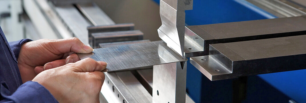
According to Stevenson (2013), any business can optimize expenses in the sheet metal bending process. In fact, there is much money wasted behind die and punch process. If an enterprise is able to invest money not only in the personnel but also in the up-to-date equipment, it is strongly recommended to make this step. Nowadays, the world is full of different modern and developing technologies that help businesses organize their production, optimize costs, automate processes, improve business operations, and increase profits. It goes without saying that the U-bending sheet metal process must be held properly in order to meet the production goals (Figure 1). For getting a better understanding of the U-bending sheet metal process, one should focus on financial issues, which is closely associated with the production process as if some parts of the sheet metal bending machine are not set up properly and cannot work as required, the process can cause numerous additional risks and expenses. As it was already emphasized, a constructor must pay close attention to all parameters in order to meet the production goals.
For example, one has to bend five sheets one-by-one meter. First of all, one has to pay close attention to sheet parameters in order to set the sheet metal bending machine properly. The average thickness of a steel sheet varies from 1.5 mm to 9 mm; in its turn, the bend length usually varies from 500 mm to 3000 mm. Inner bend radius is between 2 mm and 13 mm, while the required force is between 30 and 50 tons. (Chopra, 2015) The price of the sheet metal bending varies from 20 to 50 USD per one meter. For this experiment, five sheets metal were taken to be bent with the thickness of 1.5 mm, the length of 1000 mm, the inner radius of 4 mm, and the required force of 45 tons. According to the calculations made with the help of provided formulas, it will cost about 27-32 USD to bend one sheet metal; consequently, it will take not less than 135 USD to bend all five sheet metal.
To summarize, any business and especially a construction one should understand the importance of optimization in the industry as it helps minimize risks, raise the effectiveness of production, reduce the number of humans involved in the process and expenses required for the sheet metal bending process, improve the general performance, optimize market conditions, and, the last but not the least, adjust the whole production process.
Invite your friends and get bonus from each order they
have made!
Background
According to Brown (2014), the manufacturing process of the sheet metal bending was invented after the World War II. Thanks to the developing entrepreneurship in the United States and construction business that experienced its best times, V-shape and U-shape bending processes were developed. Later in the 1950s, a couple of private companies from London and the United States proposed the channel form that could be used in working with some ductile materials including the firm and flat metal (Brown, 2014). In the initial stage of its development, the sheet metal bending process was based on two pillars: electricity and press. Through years of practice and numerous production mistakes, sheet metal bending has developed to an atomized and up-to-date process that can be controlled with the help of a few buttons. Today, a modern enterprise needs five to seven parts of sheet metal bending machine that allows a constructor to bend this material in the required way.
The sheet metal bending process of all common types is carried out on the basis of the elastic-plastic deformation technology. In addition, it is carried out in different ways on each side of the workpiece of a sheet. This standard U-bending technology implies bending between altered layers of metal workpieces of a sheet that always remain neutral. One should note it has to be the same length as the original blank (Brown, 2014). In the classical sheet metal bending process described by Brown (2014), all narrow strips of sheet metal play a significant role and make a serious distortion of the cross section that is expressed as a reduction in the thickness of the metal bending zone. In addition, this section aims at expanding the inner corner of the manifestation in the lateral curvature. Usually, the sheet metal bending process is characterized and set up by the same features of a material alteration, but it does not imply any distortion sections as the lateral deformation reduces the main resistance of all wide (basic) sheets.
Regarding previous research in the field of the sheet metal bending, there are three authors that offer different approaches for improving the sheet metal bending process and the die and punch life, as well as optimizing parameters with the view to reducing the spring back. These scientists offer different methods for improving the sheet metal bending process, two of which are actively used in the construction business nowadays, while the last one is not that popular.
To begin with, Brown (2014) provides a theory of drawing. He claims that both the punch and die life can be extended by means of proper drawing. According to Stevenson (2013), this process can help one save the die life of a punch; meanwhile, Brown (2014) emphasizes the quality of materials and how strong a machine pushes and bends the sheet metal. Brown (2014) asserts that detailed steps of drawing allow any construction not only to save the punch and die life but also to overcome any expectations regarding the sheet metal bending process. The initial contact of the drawing is soft, and the next step is the bending. According to Brown (2014), the sheet metal bending is a complicated and sophisticated process, but one should keep in mind what actions are to be after the bending process. Detail steps of the lean drawing demonstrate (Figure 2) that straightening must be done after bending in order to toughen the sheet metal. The fourth step is the friction and compression that are responsible for the sheet thickness of the finished product, while the final shape is able to provide the exact result that has been expected at the beginning. In own research, Stevenson (2013) agrees with Brown (2014) in the idea that the step-by-step detail drawing process allows reaching the required result. However, this detailed approach requires more time, more investments, and two-three high-skilled employees in order to manage the sheet metal bending process effectively.
The following approach is offered by Forrest (2011). This researcher is not only a theorist but also a practician; he invented a unique method of the sheet metal bending and successfully patented it even through some problems arose. According to Forrest (2011), the die and punch life can be easily improved by means of optimizing appropriate parameters. It sounds very trivial and banal as the majority of construction business employees and managers do know how to set up the sheet metal bending machine in order to make it deliver desired results. However, Forrest (2011) offered to reduce standard parameters in order to save and extend the die and punch life. Forrest (2011) also claimed that spring back was deeply connected with the die and punch life; earlier, the majority of constructors and theorist used to assert that there was no connection between the spring back and die and punch life. Forrest was one of the first entrepreneurs who managed to try sheet metal bending machine with the cardboard. He mentioned that applying operation would be done on the paper (170 g / m2) or cardboard and also managed to get new parameters that would save both the die and punch life (Forrest, 2011). In addition, this method allowed minimizing the damage applied by the conventional folded protect not only folding machine but also all inner components of the sheet metal bending process. In addition, according to Bohn (2011), this method is considered one of the top approaches in the sheet metal bending process that provide the most accurate view of the printed product. Once the method was patented, he started to set experiments with the sheet metal bending. In 1988, Forrest successfully patented sheet metal bending process by applying different (reduced) parameters.
The last but not the least researchers are Shingledecker, Gandy, and Viswanathan (2011). According to them, die and punch life can be improved only by means of the strong and proper operation (Shingledecker, Gandy, & Viswanathan, 2011). The maintenance and constant care, motor oil and up-to-date parts, the most expensive equipment and other modern technologies are able to keep any enterprise up-to-date. It goes without saying that the method proposed by Shingledecker, Gandy, and Viswanathan (2011) is neither innovative nor cheap, but one cannot neglect that it is the safest, most reliable, and dependable one. Any machine (and sheet metal bending metal machine is no exception) requires a proper maintenance; it deserves timely care and service. Forrest (2011) claims that the die and punch should be changed every 2 years or one in 600 days in order to deliver excellent quality in terms of sheet metal results.
When it comes to the finite analysis of different parameters in the U-bending process, in this case, bending of a sheet metal involves the application of pressure or load (a certain amount of force) on a workpiece. It means that when using standard parameters, it is plastically deformed into the shape of the needed bend. At the same time, the structure of the metal is not altered. The basic type of such a process is considered the SMB process (sheet metal bending). It is performed without heating the metal sheet, which is usually performed by applying the pressure to the workpiece at a certain and predetermined fold line. All mentioned materials are easily bent by simple mechanical devices, more complex manufacturing cold presses. Nevertheless, one should mention that a girder rolled is often bent by the method of the hot deformation.
The most expensive, risky, labor-intensive, and professional work is the sheet metal bending that is performed by hand. This method is usually used for jewelry or decorations. Any sheet metal bending is performed according to certain rules, and the hand-made sheet metal process is no exception. A constructor is obliged to do all needed preliminary calculations of the amount of force, which is required for influencing the steel sheets. This parameter is determined by comparing the limit of the plasticity of metal with the index load, to be applied to the foldable blank.
The calculation is simple and does not take much time, but it must be done beforehand as it is mandatory. It is necessary to take into account the geometric dimensions of the steel sheets and limits of their malleability. In addition, based on the mentioned values, one has to choose according to the standard schedules or plate-recommended workload. It is important to pick up the index efforts so that it does not get too close to the limit of the metal plasticity. (Miller and Morrisey, 2007).
To summarize, there are different approaches to the sheet metal U-bending process, and all of them vary by the required time, investments, and parameters. Nevertheless, the standard sheet metal bending procedure was patented by Forrest (2011). Today, it is used in many construction businesses. It has remained the same: a sheet is disposed between the lower and upper plates of a special press or between rollers of a machine tool curly with the aim of subjecting it to a strictly controlled deformation. The technology process is demonstrated on the video (Figure 3 and 4). In the end, the sheet metal can have virtually any configuration (including complex ones). Other details can be obtained by using special equipment.
Proposed Approach
When it comes to the appropriate and innovative approach of setting the production with the view to optimizing the cost, automating processes, improving business operation, and increasing profits, one should pay attention to the K-factor. Even though K-factor is a ration of the location of the sheet line (it is connected with sheet metal thickness), there are only a few companies that offer the sheet metal bending that is performed according to the material thickness. It is totally possible to save much money and lead any enterprise to the LEAN manufacturing (lean production, lean tools) and optimize the production process, as a result. The K-factor implies the first and primary objective, to which a constructor has to pay attention, namely, the metal thickness.
In order to emphasize this argument, the most up-to-date technology in the sheet metal bending is the air bending. It is praised for being more effective and involving minimum risks both for the business and employees. If a construction business uses this type of bending, it saves not only money for the equipment and personnel but also time. With the help of the K-factor calculations, one can count minutes for how long the sheet metal must be under the die for the punch parts to get bend. Usually, the sheet metal is not thicker than 0.3 and 0.5; it is the most popular type of the sheet metal that is commonly used in modern constructions.
While in the production process, attention must be paid not only to the K-factor and air-bending as a method, there is also pushing method bending that strip metal in order to maintain the needed thickness. It implies that all flexible parts, which are made of thin blanks, produce no punches, as well as no anti-aliasing. Bending pieces of sheet metal strip of a thickness of 0.5 mm and a diameter of the round material is performed more than 4 mm with a hammer on the mandrels. The shape of the mandrel should match the shape of a flexible profile in order to avoid any deformation of the metal.
In order to perform the bending of parts that is necessary for determining the length of the workpiece, a constructor should calculate the length on the basis of a workpiece drawing. Usually, drawing details are divided into separate areas; their length is being calculated considering the radii of all bends, and then summing results in order to find the total length of a preform.
For the parts that are going to be bent at right angles without rounding on the inner side, the amount of the excess metal (in other words, general allowance) for bending will be between 0.6 and 0.8 of the metal thickness.
It is crucial to consider bending parts from strip metal and wire rod. All required parameters are to be taken into account; for instance, in order to produce a steel strip of the polygon bending at right angles without rounding the inside (Figure 5)
To summarize, attention paid to the K-factor and quintessence of the air-bending and pushing method is the most innovative and up-to-date ways to bend steep metal. K-factor was invented in the 1970s, while the air bending appeared in the market only in the 2000s. Nowadays it is widely used in the USA, Japan, and Germany. (Working with metal, 2015) In order to get a better understanding of the pushing-air bending process, one should look through the Gant chart. (Figure 7) This process describes sheet metal bending on the basis of the suggestion (to the management or client) to the design phase and sign off.
Results and Discussion
In order to focus on different parameters of the die-punch life, one should keep in mind the following effects:
· the effect of the coefficient of friction between a sheet and a punch on the die-punch life;
· the effect of the sheet thickness on the die-punch life;
· the effect of the die radius on the die-punch life;
· the effect of the clearance between a punch and a die on the die-punch life.
The effect of the coefficient of friction between a sheet and a punch on the die-punch life. In order to reduce the coefficient of friction between a sheet and a punch, one should pay close attention to the second stage of the sheet metal bending process. For reducing the power of the pushing element, the following actions should be made:
1. Splitting the polygon into individual sections and calculating their dimensions: L1 = 50 mm, L2 = 80 mm, L3 = 4 mm.
2. Calculating the total length of a workpiece with the help of the formula
3. Off with billet 132.4 mm in length and straightening it on a plate and the anvil.
4. Punching the log space for the workpiece size in width at right angles.
5. At the site of bending, the workpiece causes prescriber striper risk. The clamp at the strip should be divided in a vise between two overlaid sides.
6. Folding the shelf with the view to causing uniform hammer blows across the surface of a striker.
The effect of the coefficient of friction is used not only for calculating the metal sheet bending but also tubes made from the sheet metal. (Figure 8). In such cases, it is extremely crucial to pay attention to the coefficient of friction as, if it overcomes normal parameter, the tube can simply break (Forrest, 2011).
Bending devices significantly reduce the cost of the manual labor and improve the quality of any process treatment, for example, in manufacturing a simple hinge device or a simple tube, as it was already mentioned. The body of the sheet is inserted into the slot blank; then, the uniform blows off a hammer or pressure vise jaws on the upper edge of a workpiece in the opening device, which is bent so that it forms a loop of a specific size.
The flexible framework is reciprocating saws, and it can be performed in a special device itself. For this purpose, the workpiece is pushed under the calculated amount of stress, and as a roller screw clamp arm rises, the frame is bent at an angle of 90°. In order to facilitate the bending process, the roller is lubricated, and the arm is an extended nozzle of a piece of pipe.
An eyelet for the frame of the sheet metal bending can be made in two steps. First, the mandrel bent workpiece is made, and then, it should compress the eyelet.
As already mentioned, the most productive and accurate bending of billets is performed on bending presses and machine tools. In order to bend the tube made of sheet metal, one should pay attention to the manufacture of piping components. In the manufacture of piping components (for example, steam pipes for supply and discharge of steam, water, gas, oil pipes, and the air duct), it is often necessary to obtain a large number of curved sections of a pipe under curved angles in one or more planes.

Top Writer Your order will be assigned to the most experienced writer in the relevant discipline. The highly demanded expert, one of our top 10 writers with the highest rate among the customers.
Hire a top writer for $4.40Effect of Sheet Thickness of Die-Punch Life
The thickness is one of the most important parameters in the sheet metal bending. In order to avoid any problems and, most importantly, to extend the die-punch life, there is a method that offers to wider the steel pipes and tubes that are made of the sheet metal. Depending on the thickness of the material, the diameter and bend radius of sheet metal (or pipes) is performed with or without filler. Filling in the pipe wall protects against the formation of folds in the ground bending wrinkles (flutes). The filler used is small and well-dried sand, which is poured into the tube in a molten state or right on the sheet metal (Forrest, 2011).
Cold bending of the sheet metal with filler is suggested for maintaining the described procedure: one end of the sheet metal should be a tightly scored wooden stopper, and a second sheet metal must be filled with sand. When filling, the sheet metal must be rotated and rattling hammer from top to bottom in order to compact the sand inside the pipe. While filling the pipe with the sand, the other end should be at a stopper (Figure 9). Thereafter, the chalk outlines the bending location and is then inserted into the pipe attachment so that the weld seam (if the pipe is not extruded) is aside. With this setting, pipes need to be taken at the long end and gently bend at a predetermined angle. After checking the correctness of bending, the pattern has to be cleared, and a free from the sand pipe should be blown with the compressed air. It helps avoid the effect of the sheet thickness of the die-punch life; no matter what thickness of the sheet metal is chosen, the result will meet expectations.
According to Forrest (2011), in a heated condition, a flexible pipe is typically performed with filler. The preparation (making stoppers, their insertion in pipe holes, and filling the tube, for example) is usually performed in the same manner as in the previous one. In order to exit through holes, the particles of gasses in the tubes must be made smaller. Otherwise, the pipe rupture can occur, or wooden plugs can fly.
In practice of the pipe bending, the heated portion of the length of the take in bending at an angle of 90° is equal to 6d; at an angle of 60° is equal to 4d, and at an angle of 45 ° is equal to 3d. Heating steel pipes produce the flame of a blowtorch, gas burner in the furnace and high-frequency currents (for instance. In. H.) to the dark red color, and then set the tube into the device and is bent to a predetermined angle. After removing the pipe from the device, it is allowed to cool down; then, the plug hole is knocked out, and the sand is poured. Bending control is performed correctly or references the pattern tube.
Effect of Die Radius on Die-Punch Life
As it was already mentioned, the die radius has a negative influence on the die-punch life. In order to avoid this effect, Stevenson (2013) offered a flexible pipe method, in which the sheet metal is being bent by means of the flexible pipe. The flexible pipe is often performed manually by such a device as a plate with holes, in which pins are installed where required. These pins serve as stops that are required for bending the pipes. This device can be used for bending pipes of different diameters. Roller devices are also used for various designs (Stevenson, 2013). It is shown in an example of a special device for bending pipes of the same diameter. It consists of two clips” the fixed and mobile ones, which are mounted in the plug. The fork and fixed roller are situated on a common axis that is reinforced at the base. The end of the tube is pressed against the bracket to the stationary roller and turning the handle bends the tube roller for a given radius. The grooves (streams) on the rollers depend on the diameter of a bent pipe. The device is attached to the base of the bench. (Chopra, 2015)
According to Bohm (1971), more applications are finding new ways for the pipe bending: bending with stretching and bending the blank with the induction heating (heating high-frequency currents). In the bending with stretching, a preform is subjected to tensile stresses that exceed the yield strength of the metal on the stretched state bend. It is applied in the bending process in the manufacture of various parts of aircraft, buses, railway, tram cars, sea and river vessels, agricultural machinery that are manufactured from carbon and alloy steels, as well as aluminum, magnesium, copper, and titanium alloys. The bending is carried out on the bending and stretching machine with a rotary table. The advantage of this process as compared to the conventional method of bending blanks is that the blank after bending is not springy. Also, less power is required in the manufacture of the equipment components.
Effect of the Clearance between a Punch and a Die on the Die-Punch Life
The last but not the least effect is the effect of the clearance between a punch and a die on the die-punch life. Miller and Morrisey (2007) offer using the most widespread medium model of the machine for bending tubes with outside diameters from 95 mm to 300 mm in order to keep balance in the LEAN manufacturing. The installation comprises two parts: mechanical and electrical ones. A mechanical part is an actual machine for bending pipes as the electrical part of the machine consists of a high-frequency electrical item and installation.
The machine includes a welded box-type frame, on which the pipe clamp carriage, the longitudinal feeding mechanism, the carriage guide rollers of the pressing roller carriage, and an inductor for induction heating pipe are placed. In its turn, the clamping carriage serves for fastening the tube to the machine. It moves along the bed spindle longitudinal feed mechanism. There are two jaws, one of which is movable and clamps the pipe on a carriage. The movable jaw is brought into action by a screw handle by hand and presses the pipe to the fixed jaw. Bent pipe axis is eccentric with respect to the frame. The magnitude of eccentricity varies for pipes of different diameters.
The carriage guide roller serves for guiding the movement of the pipe in the bending process and receiving the reaction force from the same. It moves the two lead screws, interconnected bevel gear. One of the guide rollers is mounted on the slide and can be moved manually by a screw. Both rollers are free to rotate on their axes. Guide rollers on the carriage holder are fixed with an inductor, a high-frequency transformer (not shown), and some elements of the cooling system.
The carriages of the pressure roller are fixed. On the carriage base, the slide with pressed-axis moves and rotates a pressure roller. Moving the slider by means of a lead screw that is rotated by the drive of a transverse feeder. On pressing, the roller carriage has two conical breakers for limiting the stroke of the clamping roller depending on the bending radius. The transverse feed mechanism transmits this rotation to the lead screw by a chain of transmissions. However, experience has shown that it is advisable to replace the chain drive on the Gear. The replacement inductor for heating the pipe is a ring of copper tube, which is cooled by the water that is supplied via a flexible hose.
For the additional support of the pipe bend to the machine, there is a special roller that can be moved by a handle according to the pipe length. When this part is particularly long, special extensions are used for supporting the hanging of the pipe. The heating of a pipe reaches a temperature of 900- 1000°C. The machine design requires the inclusion of the longitudinal feed of the pressing roller only when the temperature reaches 700-750°C; it allows avoiding the overheating of the pipe material at the beginning of the bending process. The pipe is installed on the machine, clamped jaws, and the guide rollers; for closing it manually, one has to rotate the screw of the supplied pressure roller.
When the current generator is in the place of the inductor arrangement, the pipe heated belt is three to five times wider than the thickness of the tube. Then, with the help of the longitudinal feeder, the pipe begins to move along the roller machine. However, the movement begins, and the roller is pressed. Thus, in the bending process, for instance, in E. Tensile and compressive outer side on the inner side, there is a narrow annular strip tube. The process is affected by the bending forces that are generated by mechanisms of the longitudinal feed tube and those that are generated by moving the pressing roller by the curved pipe portion that is turned by the pressing roller. The pipe bending machine are continuously carried out in a serial process, in which heating, bending, and cooling are carried out sequentially and continuously. Bending tubes with the help of high-frequency currents has the following advantages. The roundness of the pipe at the point of bending receives less than in the case of using other methods. It occurs directly in the heated metal, while in all other approaches, the heat is brought from the heated metal environment. Such heat transfer method reduces the time that is required for heating, and the heat loss to the environment. The total time that is required for a single bend at 90°C depending on the diameter and wall thickness of the bend mother pipe is only 9,5-14 min. instead of 54 minutes. Bending is made at the plate. Therefore, if an average shift on the plate can be performed only 8-9 bends radius of at least 3.5-4 bent pipe diameters, the machine with heating t. In. h., one can get up to 38 bends with a bending radius that is equal to the diameter of the pipe of 1.5-2.
The induction heating method allows mechanizing and largely automating the process of bending. Finally, it eliminates the time-consuming and lengthy operation pack sand pipes. The rolling tube extends the operation (tightness) of the internal diameter on the ends of a pipe in order to strengthen its flanges, nipples, and other parts. It is performed with the help of a special instrumental rolling. Rolling can be carried out manually by using rolling machines and machine tools. Rolling has tapered rollers that are impaled on a steel rod, one end of which is formed by a cone, and the other is square head for the gripping knob. The rod periodically feds forward hollow screwed into the thread of the housing. Feeding is carried out at least to ease the pressure rollers on the pipe wall. The screw is kept from moving the setting ring. In the process of expanding, the end of the pipe flange wear with machined grooves in this hole and then is inserted into the tube with rolling the rollers and appropriate rotation. With the help of rollers that are impaled on a cone, the pipe will produce the rolling while pressing it in the metal flange groove (Miller & Morrisey, 2007)
Struggling with your essay?
Ask professionals to help you!
Start Chat
Conclusion
To summarize, the sheet metal bending process has been widely used in the construction business for many years already. Nowadays, there are many types of the sheet metal bending process, which vary by price, required investments of labor, some risks, and other factors. For the time being, paying attention to the K-factor and air-push bending are claimed to be the latter-day technology that helps many enterprises save time and money.
Any entrepreneur or production manager should understand that the sheet metal bending process requires calculations and preoperational activities that take more than 70 percent of all resources. Even though these preliminary processes look complicated, a constructor can calculate the sheet metal bending process with the help of the Gantt chart. Today, there are not only many technologies for the sheet metal bending process but also numerous forms that allow constructors to bend any sheet metal without a huge investment. In addition to some popular methods of the sheet metal bending, a number of up-to-date approaches are described in the paper, for instance, the U-bending process. These latter-day developments have to be further researched, discussed, and tested in order to provide new technologies for the sheet metal bending process.